Mastering DIY Tool Mount Fabrication: Essential Technical Specifications and DXF Files
Introduction to DIY Fabrication
Successful tool storage DIY starts with clear technical fabrication specifications. Before you cut, define the load case, material, thickness, hole pattern, hardware, and finish. This ensures your custom tool mounts fit the system you use, carry the expected weight, and assemble without rework.
Choose materials based on strength-to-weight and corrosion needs:
Mild steel: 12–10 ga (0.105–0.135 in) for heavy-duty plates and brackets; economical and rigid.
5052-H32 aluminum: 3–4 mm for lighter assemblies; good corrosion resistance, easier to machine.
304 stainless: 2–3 mm when maximum corrosion resistance is required.
Account for finish. Powder coat typically adds 0.002–0.004 in per side; increase hole clearances 0.1–0.3 mm to prevent interference after coating. Deburr edges and add small corner radii (1.5–3 mm) to reduce chipping and snag points.
Define precision cutting dimensions with the fasteners in mind:
M6 clearance holes: 6.6–7.0 mm; 90° countersink for M6 flat-head: ~11.0–11.5 mm major diameter.
Edge distance: ≥1.5× hole diameter (2.0× preferred) to prevent tear-out.
Rivnuts: check grip range; typical M6 requires ~9.0 mm hole—confirm with the insert spec.
If your plate interfaces with a modular system (e.g., packable boxes, rails, or van panels), lock down center-to-center spacing and datums. Keep patterns in round increments (metric: 25/50 mm; imperial: 1/2 in or 1 in) and tolerance critical hole locations to ±0.25 mm (±0.010 in).
Prepare fabrication DXF files that are machine-ready:
Units: mm or in—state explicitly; set origin at a meaningful datum.
Geometry: closed polylines; no splines; purge duplicates and tiny segments.
Layers: CUT, ETCH, BEND; no dimensions or text on CUT.
Kerf: do not pre-compensate unless your shop requests it.
Export: DXF R12/R14 for broad compatibility; include a simple title block with material, thickness, finish, and revision.
Well-structured metal fabrication guides and precise DXF drawings reduce scrap, speed turnaround, and yield custom tool mounts that install cleanly and stay secure in the field.
Why Technical Specifications Matter
Technical fabrication specifications are the bridge between a sketch and a reliable, field-ready mount. For custom tool mounts that must lock into popular storage systems and survive daily transport, spec discipline prevents misfits, rattles, and premature wear.
Critical details to define before cutting:
Interface and pattern: Call out the manufacturer’s mounting pattern, datum references, and positional tolerance (e.g., ±0.25 mm/±0.010 in on interface slots). Note hole types (clearance, countersink, counterbore) and any slot orientations that allow adjustability.
Material and thickness: Select thickness by load and span. Example: 12 ga steel (~2.6 mm) for high-load plates; 3–4 mm aluminum to reduce weight with added ribbing. Include alloy/temper and grain direction if bending.
Finish and coating: Powder coat thickness typically 50–100 microns (2–4 mil). Add coating allowance to sliding fits and latch interfaces; widen slots by 0.1–0.2 mm when needed. Specify color, texture, and masking zones.
Hardware spec: Define thread standard (M6 x 1.0 vs 1/4-20), head style, washer use, and torque. Countersink angle matters (82° imperial vs 90° metric); mismatch leads to proud heads or looseness.
Edge and safety: Deburr; add 0.5–1.0 mm edge breaks or 1–2 mm corner radii to reduce snags and coating failure. Minimum inside bend radius typically ≥1.0t for steel, ≥1.5t for aluminum to avoid cracking.
Cutting and tolerances: State precision cutting dimensions and process capability. Typical laser ±0.1–0.2 mm; waterjet ±0.2–0.3 mm; plasma ±0.4–0.8 mm. Note that kerf compensation is applied in CAM, not baked into geometry.
Structural performance: Define allowable deflection under load (e.g., <1.5 mm at 20 kg). Consider gussets, flanges, or cross-members to stiffen wide spans.
Clearance and access: Model latch travel, handle swing, and battery pack removal. Maintain 0.5–1.0 mm per side for coated mating features to avoid binding.
For fabrication DXF files, include:
Units (mm or in), origin, and layer naming (CUT, ETCH, BEND).
Closed polylines, no duplicates, no splines; convert text to etch geometry.
Bend notes on a non-cut layer per metal fabrication guides.
Well-formed technical fabrication specifications shorten iteration cycles, ensure repeatable fits, and elevate tool storage DIY projects from “works once” to professional-grade.
Understanding DXF Files for Fabrication
DXF is the de facto exchange format for transferring 2D profiles into CAM. For cutting clean, accurate custom tool mounts, start with fabrication DXF files that match your technical fabrication specifications and the process you’ll use (laser, waterjet, plasma, or CNC router).
Key items to verify before you cut:
Units and scale: The file should be 1:1 in either inches or millimeters—no unitless geometry. A quick check is a known feature (e.g., a 100 mm slot) measured in your CAD.
Geometry quality: Use closed polylines and arcs only; avoid splines and text as geometry. Remove duplicates, tiny gaps, and zero-length entities. Set all contours to zero line width.
Layers by operation: At minimum, separate CUT (through-cuts) from ETCH/MARK (logos, bend notes) and BEND (bend centerlines). Ensure BEND lines are non-cut (different color/layer) so the CAM doesn’t pierce them.
Precision cutting dimensions and tolerances: Typical shop capabilities are ±0.005–0.010 in (±0.13–0.25 mm) for laser, ±0.010–0.020 in for waterjet, and looser for plasma. Reflect this in hole sizes and tab fits.
Hardware and fit examples for tool storage DIY:
Clearance holes: M6 bolt → 6.6–7.0 mm hole; 1/4-20 bolt → 0.266–0.281 in hole. Oversize an extra 0.1–0.2 mm if parts will be powder-coated.
Slots for adjustability: For M8 hardware, 9.0 mm slot width; slot length 18–25 mm depending on range. Use radiused ends (≥ tool kerf radius) to reduce stress risers.
Edge distance: Keep hole center ≥1.5× diameter from the edge on steel plates used for load-bearing custom tool mounts.
Process allowances:
Kerf/offset: Don’t draw lead-ins or kerf in the DXF; let CAM apply them. Typical kerf: laser 0.008–0.020 in, waterjet 0.015–0.040 in, plasma 0.040–0.080 in.
Bend compensation: If your DXF includes flat patterns, specify material, thickness, inside radius, and K-factor (e.g., 11 ga steel, 0.120 in, Ri = 0.12 in, K = 0.38) so shops can reproduce bends accurately.
Finish allowance: Powder coat adds 0.002–0.004 in per face; add 0.005–0.010 in total clearance to interlocking tabs or sliding features.
Compatibility and handoff:
Save/export as ASCII DXF R12 or 2000 for maximum machine compatibility.
Put the part origin at a logical corner; keep geometry near the origin for easy nesting.
Include a one-page note with material (e.g., 10–12 ga steel for heavy-duty mounts), quantity, and any tapped holes or countersinks to avoid misinterpretation.
These metal fabrication guides ensure your fabrication DXF files move from screen to shop floor without surprises—and that your mounts fit first time.
Key Dimensions and Tolerances
Dialing in technical fabrication specifications early prevents fit-up surprises and speeds assembly. For custom tool mounts, prioritize the features below before cutting metal.
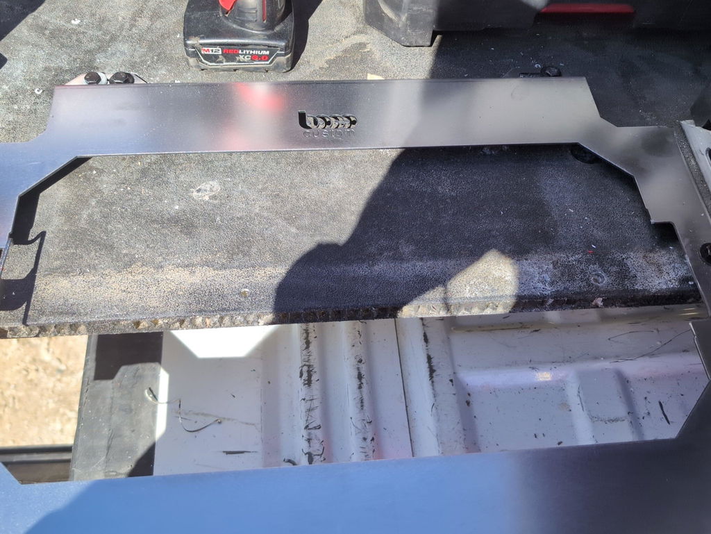
Illustration for Mastering DIY Tool Mount Fabrication: Essential Technical Specifications and DXF Files
Core dimensions to lock in
Material thickness: choose based on load and stiffness. Common plates are 3.0–4.8 mm (0.118–0.188 in) steel. Match the thickness specified in the fabrication DXF files to preserve fit with mating hardware.
Overall footprint: size to the storage surface with 3–5 mm (0.125–0.187 in) margin from edges for powder-coat wrap and safe edge distance.
Hole/slot interfaces:
- Clearance holes: 1/4-20 = 6.8–6.9 mm (0.268–0.272 in); M6 = 6.6–6.8 mm (0.260–0.268 in).
- Elongated slots for adjustability: width = fastener clearance; length = clearance + 3–6 mm (0.125–0.250 in).
- Countersinks: 82° for imperial flat-heads, 90° for metric. Depth to flush the head diameter (e.g., 1/4 in flat-head Ø ≈ 13.5 mm/0.531 in).
Tolerances that keep mounts aligned
Overall length/width: ±0.25–0.50 mm (±0.010–0.020 in).
Hole diameter: ±0.08–0.13 mm (±0.003–0.005 in).
Hole-to-hole position: ±0.13–0.25 mm (±0.005–0.010 in).
Flatness after cutting/finishing: ≤1.5 mm over 600 mm (≤0.060 in over 24 in).
Edge distance: ≥2× material thickness or ≥10 mm (0.394 in), whichever is larger.
Precision cutting dimensions and process notes
Laser kerf: 0.20–0.40 mm (0.008–0.015 in). Offset inside features smaller; keep lead-ins 2–3 mm (0.080–0.125 in) away from critical edges.
Minimum slot/bridge width: ≥ material thickness + kerf to avoid tip-ups.
Deburr both sides; add 0.5–1.0 mm (0.020–0.040 in) corner radii to reduce coating thin-out.
Finish allowances for tool storage DIY
Powder coat builds 50–100 μm (2–4 mil) per face. Oversize precision holes by 0.10–0.20 mm (0.004–0.008 in) or mask holes/threads before coating.
Tap after coating when threads are required: 1/4-20 tap drill #7 (5.10 mm/0.201 in); M6×1 tap drill 5.0 mm.
DXF fidelity tips
Verify unit scale (1 unit = 1 mm or 1 in) and remove duplicate/overlapping entities.
Use separate layers for CUT and ETCH; keep bend or datum marks as etch only.
Dimension from logical datums; inspect center-to-center distances rather than edge-to-hole when possible.
These metal fabrication guides ensure your precision cutting dimensions translate into reliable, low-profile mounts that fit right the first time.
Material Selection for Durability
Choosing the right material starts with the load case, environment, and forming method. Your technical fabrication specifications should call out alloy, thickness, finish, and hardware interface so your custom tool mounts don’t deform, corrode, or loosen under vibration.
Steel (A36/HRPO or CR)
Best all-around for truck beds, vans, and shop walls due to stiffness and weldability.
Thickness: 12 ga (0.105 in) for moderate loads; 10 ga (0.135 in) for heavy Packout-style plates; 3/16 in when spans exceed 18 in without flanges.
Finish: powder coat over phosphate pretreatment for abrasion and corrosion resistance.
Cutting: laser yields tight edge and minimal HAZ; plan kerf 0.008–0.016 in in your precision cutting dimensions.
Stainless (304)
Use for coastal, washdown, or chemical exposure where coatings may chip.
Thickness: same as steel, but expect slightly more flex; add return flanges or ribs.
Aluminum (5052-H32 for formed parts, 6061-T6 for machined plates)
Weight-sensitive builds or non-ferrous environments.
Match steel stiffness by increasing thickness: 0.125–0.190 in for plates mounting power tool cases.
Bend radius: 5052 inside radius ≥ 1t; 6061 ≥ 1.5–2t to prevent cracking.
Isolate from steel (nylon washers/bushings) to mitigate galvanic corrosion.
Fasteners and inserts
PEM self-clinching nuts: confirm minimum sheet thickness (e.g., M6 requires ≥ 0.040 in). Specify hole size per manufacturer in your fabrication DXF files.
Rivnuts: pick grip range to match plate thickness; for 10 ga steel, 1/4-20 or M6 with 0.5–0.7 turn set is typical.
Clearance holes: M6 = 6.6–7.0 mm; 1/4-20 = 0.266 in. Use short slots (length +1–2 mm) for fit-up tolerance.
Structural detailing
Add 0.75–1.0 in return flanges to reduce deflection on spans; K-factor 0.38–0.45 for steel in metal fabrication guides.
Maintain minimum web width ≥ 2x material thickness around slots.
Deburr/radius edges before coating to improve adhesion and reduce wear on mating plastic cases.
For tool storage DIY projects, include material notes directly on DXF layers (alloy, thickness, bend radii) so shop operators cut and form exactly to spec without guessing.
Powder Coating and Finishing Tips
Powder coating adds durability and corrosion resistance to custom tool mounts, but it also affects fit. Build finishing into your technical fabrication specifications so parts snap into storage systems without binding and withstand jobsite abuse.
Surface prep
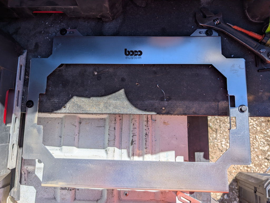
Illustration for Mastering DIY Tool Mount Fabrication: Essential Technical Specifications and DXF Files
Degrease thoroughly (alkaline wash or solvent), remove weld spatter, and break sharp edges with a light chamfer or Scotch-Brite. Aim for a consistent surface to avoid telegraphing under gloss finishes.
For carbon steel weldments, pre-bake at 375–400°F (190–205°C) for 30–60 minutes to outgas and reduce pinholes.
Coating allowance and precision
Typical single-coat thickness is 2–4 mil (0.002–0.004 in / 50–100 µm). That’s per side, so internal features close by 4–8 mil total.
Adjust precision cutting dimensions in your fabrication DXF files accordingly. Example: if a slot must clear an 8.00 mm tab after coating, oversize the slot to ~8.30–8.40 mm to account for 0.10–0.20 mm coating on each face.
For tight interfaces (e.g., latch tongues on tool storage DIY systems), design “no-coat” pads and keep them masked to maintain low-profile engagement.
Masking strategy
Call out mask zones in your DXF as a separate layer (MASK_KEEPOUT). Mask threads, grounding points, mating faces, and bearing surfaces.
Use silicone plugs for tapped holes and high-temp tape on flats. Tap or chase threads post-coat only if masking isn’t feasible.
Hanging and grounding
Include a dedicated 3–4 mm hang/ground hole in a non-critical area. Ensure solid electrical contact to avoid Faraday-cage thin spots in deep pockets.
Orient parts to shed powder and prevent sags; avoid hidden cavities that trap powder.
Cure schedule
Follow the powder manufacturer’s TDS (commonly 10 minutes at 375–400°F/190–205°C at metal temperature). Verify with a contact thermometer—oven air temp isn’t enough.
Finish selection
Polyester TGIC is a good all-around exterior choice; epoxy-polyester hybrids offer chemical resistance for shop use.
Fine-texture black hides fabrication marks and fingerprints; matte reduces glare inside trucks; bright safety colors improve visibility.
Quality checks
Test-fit critical interfaces before coating and again after cure using go/no-go gauges.
Measure film thickness with a comb gauge and document results in your metal fabrication guides to keep builds repeatable.
Tools and Equipment for Fabrication
Turning technical fabrication specifications and fabrication DXF files into reliable custom tool mounts starts with the right tooling and setup. Choose equipment that matches your material, tolerance, and throughput needs, then calibrate for precision cutting dimensions before the first cut.
Cutting systems:
CNC laser: Best for ±0.005–0.010 in tolerance, small features, and clean edges. Typical kerf 0.006–0.012 in; compensate in CAM and use 0.02–0.06 in lead-ins.
CNC plasma: Cost-effective for 10–12 ga steel. Expect ~0.040 in kerf; keep minimum hole diameter at 1–1.5× material thickness to preserve roundness.
Waterjet: No heat-affected zone; ideal for laminated assemblies or stainless. Kerf ~0.020 in; slower but extremely accurate.
Fabrication essentials:
Workholding and layout: Flat weld table, toe clamps, magnetic squares, scribe, transfer punches, digital calipers, machinist square.
Drilling and tapping: Drill press, quality bits, and lubricants. Common tap drill sizes: 1/4-20 uses #7 (0.201 in); M6×1.0 uses 5.0 mm. Countersink 82° for SAE flatheads; 90° for metric.
Forming: Box/pan brake with dies matching 1× material thickness inside radius. Start with K-factor 0.38 for mild steel; verify bend allowance on a test coupon.
Welding: MIG for speed on mild steel; TIG for thin sections or stainless. Stitch weld tabs to limit distortion.
Hardware: Rivnut/nutsert tool (1/4-20, M6), press for PEM-style self-clinching nuts, Grade 8.8/M8.8 hardware, nyloc nuts, and washers.
Finishing: Deburring wheels, chamfer tools, media blast or phosphate wash, powder coat gun, and an oven. Many powders cure at 400°F metal temp for 10 minutes; follow manufacturer data.
Safety: Shield, respirator, cut-resistant gloves, hearing protection, and proper ventilation/drying for air systems.
Materials:
Mild steel 10–14 ga for heavy-duty mounts; 5052-H32 aluminum 0.090–0.125 in for lighter builds; 304 stainless 16 ga where corrosion resistance matters.
Quality checks:
Verify slot width and hole patterns against your tool storage DIY layout with go/no-go gauges.
Target ±0.010–0.015 in on critical interfaces; oversize slots by 0.010–0.020 in for field fitment.
Dry-fit to your system before coating.
When using Boco Custom fabrication DXF files, align machine settings to the noted dimensions and any included metal fabrication guides to preserve fit, strength, and low-profile clearance.
Safety Practices in the Workshop
Safety is part of your technical fabrication specifications, not an afterthought. Treat every step—from importing fabrication DXF files to final assembly of custom tool mounts—as a controlled process that prevents injury and protects your work.
Before you cut
Verify DXF units and scale (in vs mm). Open a 1-inch/25.4 mm known feature to confirm. Incorrect units are a common cause of miscuts.
Apply kerf compensation and lead-ins; cut internal features before external profiles to prevent part shift. Add tabs on small parts to avoid tip-up.
Dry-run your toolpath with the torch/laser disabled. Check clearance, pierce locations, and precision cutting dimensions.
Secure the sheet on a flat, supported bed; manage offcuts so they don’t bind or fall.
Personal protective equipment
Eye/face: Safety glasses with side shields; add a face shield for grinding or wire brushing.
Hearing: Earplugs or muffs for grinders, saws, and CNC plasma.
Respiratory: P100 for grinding; P100 + organic vapor cartridges for solvents/paints; use a downdraft or water table and cross-ventilation when cutting.
Hands: Cut-resistant gloves (ANSI A5+) for handling sheet; remove gloves near rotating spindles to avoid entanglement.
Body/feet: Non-flammable clothing, sleeves down, and safety-toe boots.
Machine, fire, and electrical safety
Inspect guards, e-stops, cables, and ground clamps before power-up.
Clamp work; never hand-hold near a bit, wheel, or torch.
Keep flammables out of the hot-work zone; maintain a fire watch and keep an ABC extinguisher close.
Manage cords and hoses to prevent trips; lockout/tagout during maintenance.
Material handling and finishing
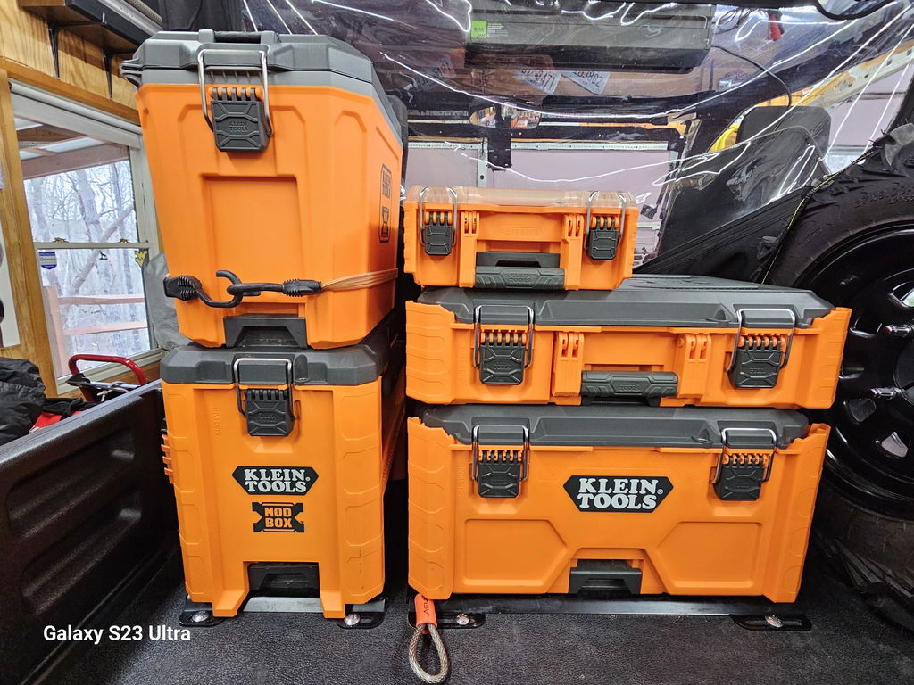
Illustration for Mastering DIY Tool Mount Fabrication: Essential Technical Specifications and DXF Files
Use team lifts, magnets, or hooks for heavy plate. Deburr and break edges 0.3–0.5 mm to remove sharp burrs.
De-oil before coating; if powder coating, use a dedicated non-food oven and ensure part grounding to avoid arcing.
Assembly for tool storage DIY
Deburr holes; use quality hardware with nyloc nuts or threadlocker. Torque per fastener grade and lubrication.
Test-fit with unloaded tools; confirm latch clearances. Static load-test mounts to at least the expected service load before road use.
Document these steps in your metal fabrication guides. Consistent safety practices improve quality and throughput while honoring the intent of your technical specs.
Benefits of Custom Tool Solutions
Custom solutions let you design around the way you actually work. When technical fabrication specifications are paired with fabrication DXF files, you get custom tool mounts that fit your storage system, protect your gear, and speed up installs.
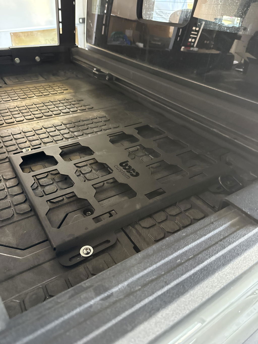
Exact fit and compatibility. Precision cutting dimensions capture hole patterns, clearances, and alignment for major tool storage ecosystems and van racking. Low-profile plates prevent drawer interference and reduce snag points. Example: a charger mount that clears cord strain reliefs while aligning with existing rack slots.
Repeatable accuracy at scale. DXF geometry drives laser, waterjet, or CNC plasma directly, eliminating layout guesswork. Features like centerlines, mirrored patterns, and tab-and-slot indexing make batch runs consistent and easy to fixture.
Strength-to-weight optimization. Choose thickness and alloys to match load. Common approaches: 11–14 ga steel for high stiffness, or 5052-H32 aluminum for weight savings. Add gussets, hem flanges, and generous inside radii (≥ material thickness) to mitigate fatigue—best practices often highlighted in metal fabrication guides.
Faster, safer installs. Predefined anchor points for rivnuts/PlusNuts or carriage bolts speed mounting to shelves, carts, and van walls. Securement reduces rattle and impact shock to nailers, impacts, and batteries during transport.
Durable finish and identification. Powder-coated parts resist corrosion and abrasion. Color-coding and cut-in labels help technicians return tools to the right bay, improving accountability.
Cost control and easy revisions. Update a DXF to accommodate a new tool profile without retooling. Reuse hole patterns across different mounts to simplify hardware and inventory.
Documentation that travels with the part. Baseline technical fabrication specifications support QA checks, BOMs, and subcontractor handoffs, ensuring every shop cuts the same part.
For tool storage DIY, this approach yields professional results: clean, low-profile mounts that integrate with your existing system, withstand daily jobsite abuse, and can be reproduced on demand whenever your kit evolves.
Getting Started with Boco Custom Files
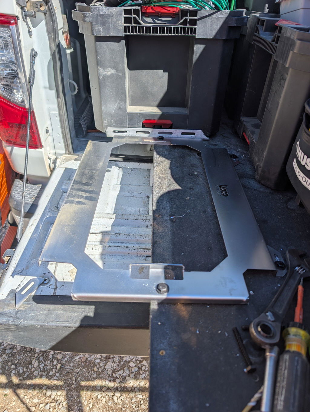
Boco Custom’s fabrication DXF files are built for pros who want precision without guesswork. Each file is CNC-ready for laser, waterjet, or plasma and mirrors the low-profile, secure designs used in the company’s heavy-duty mounting plates. Downloads are instant, so you can move from purchase to cutting with no downtime.
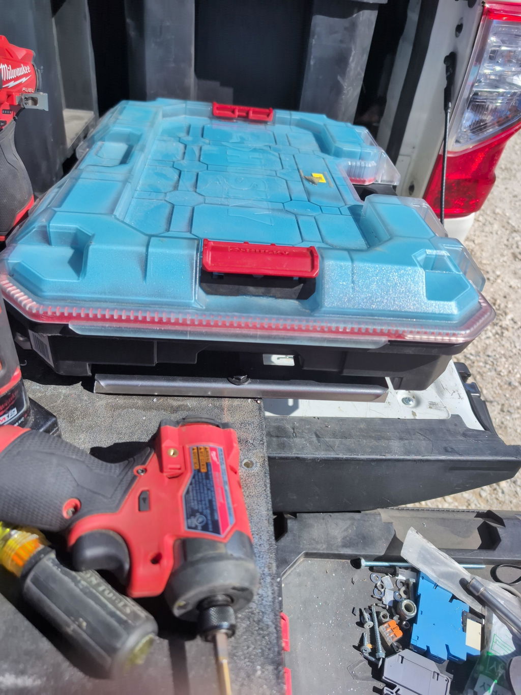
Start by selecting the model that matches your tool system and mounting method. If you’re building custom tool mounts for a Milwaukee Packout setup, a van bulkhead, or a shop wall grid, verify the pattern, latch clearances, and footprint against your storage layout before nesting.
Key checks before you cut:
Units and scale: Confirm the DXF opens at 1:1 in your CAD/CAM (often inches). Avoid auto-scaling.
Precision cutting dimensions: Cross‑check critical hole diameters and slot lengths against your fasteners and anchors. Apply kerf offset in CAM to hit nominal sizes.
Process allowances: Set pierce lead‑ins, cut paths, and bridge tabs appropriate to your machine and material.
Edge quality: For plasma, consider a finish pass on tight holes. For laser/waterjet, maintain slowdowns on small radii to preserve tolerance.
Material selection should align with your load and mounting surface. Many tool storage DIY builders choose mild steel in the 10–14 ga range for weight savings, stepping up to thicker plate for high-vibration installs. If you prefer a finished part, Boco Custom’s powder‑coated plates deliver proven durability with same‑day shipping and local pickup options.
Fastener strategy matters as much as plate strength:
Use quality hardware (e.g., nylock nuts or threadlocker) for mobile rigs.
Pair slots with fender washers to accommodate on‑site adjustment.
Isolate dissimilar metals to limit corrosion in vehicle installs.
Finish for longevity. Deburr inside and outside edges, break sharp corners, and prep for coating. Powder coating replicates the abrasion resistance of Boco’s production plates; zinc‑rich primer undercoat helps in salty or wet environments.
Do a quick dry fit with clamps before final torque. A 10‑minute check prevents misalignment and preserves the technical fabrication specifications you planned for—delivering clean, repeatable results from your fabrication DXF files and metal fabrication guides.
Conclusion: Elevate Your Tool Organization
Dialing in technical fabrication specifications and pairing them with reliable fabrication DXF files is the fastest path to durable, low-profile results. Whether you’re outfitting a service truck or a shop cart, the difference shows up in smoother installs, repeatable fit, and fewer reworks.
Carry these proven specs into your next set of custom tool mounts:
Material: 11–12 ga steel (0.120–0.105 in) for high load; 0.125 in 5052-H32 aluminum when weight savings matter. If you need tapped holes in sheet, use 0.125 in+ or switch to rivnuts.
Precision cutting dimensions: Compensate for kerf (fiber laser ~0.006–0.012 in; waterjet ~0.010–0.020 in). Add slot/tab clearance of +0.006–0.015 in depending on process and coating.
Hole sizing: 1/4-20 rivnut holes typically 0.375 in; M6 rivnut holes ~9.0 mm. Use 82° countersinks for imperial flat-head screws, 90° for metric. For clearance, size 1/4 in hardware at 0.281 in, M6 at 6.6–6.8 mm.
Bends: Start with inside bend radius ≈ material thickness and a K-factor of 0.42 for 5052 and mild steel. Add rectangular bend reliefs at least material thickness wide, carried to the bend tangent.
Edge treatment: Deburr and break edges (0.010–0.020 in chamfer or 0.5 mm radius) to protect tool cases and hands.
Coatings: Powder coat adds ~2–4 mil per side. Oversize holes by +0.010–0.015 in and widen tight slots accordingly. Mask grounding points for solid electrical contact.
Interfaces: Keep latch and handle clearances generous; avoid fastener heads protruding into engagement paths by using low-profile hardware.
Boco Custom’s DXF files embed these metal fabrication guides into clean geometry—clear datums, labeled CUT/ETCH/FORM layers, bend notes, and units called out—so your shop can move from nesting to cutting with confidence. If you’re doing tool storage DIY, start from verified precision cutting dimensions instead of redrawing from scratch.
Prefer ready-to-run? Boco Custom manufactures powder-coated, heavy-duty, low-profile mounting plates for major tool systems with same-day shipping and local pickup options. Or download the DXFs instantly and fabricate in-house on your schedule.
Elevate organization, reduce build time, and hit spec the first time—choose vetted files and hardware-ready plates engineered for the job.
Standard shipping takes 5 to 7 business days. Express (2 to 3 days) and overnight options are available at checkout. Orders over $50 ship free.
Can I order online and pick up in store?
Yes. Select "Pick up in store" at checkout and choose your nearest location. Most orders are ready within 2 hours.
What if my order arrives damaged?
Contact us within 7 days of delivery with your order number and a photo. We'll arrange a replacement or refund, no return shipping required.
AI-Generated Content Disclosure
This blog post was created with the assistance of RankGPT, an AI-powered tool designed to generate high-quality, SEO-optimized content at scale.
As a small business embracing modern technology, we use AI to help us:
Produce informative articles more efficiently
Increase our online visibility through better performance in traditional search engines (like Google) as well as emerging AI-powered searches and answer engines
Reach more potential customers and grow our presence in a competitive digital landscape
By leveraging tools like RankGPT, we're able to publish valuable content more consistently and scale our efforts in ways that would otherwise take significantly more time and resources.
Important notes for readers:
While RankGPT helps create well-structured and relevant content based on current best practices, AI-generated posts are not always 100% accurate, complete, or free from errors.
The information, opinions, and perspectives expressed may not fully reflect the exact views, experiences, or official positions of Boco Custom, its team members, or the individuals involved in our business.
AI content should be viewed as a starting point or general resource—not as personalized professional advice, definitive facts, or a substitute for direct consultation with us or qualified experts.
We always recommend verifying important details independently, especially for decisions related to custom products, services, or any business matters.
We are committed to transparency and continually work to improve our content. If you have questions, feedback, or spot any inaccuracies, please reach out—we genuinely appreciate it!
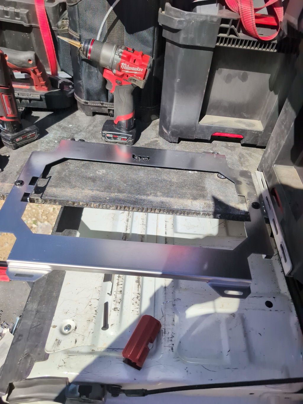
Not only is this way overbuilt for the price with its solid, confident craftsmanship, I am completely convinced that these guys are the best around when it comes to the packout platform.
I like these, they are much more compact than what Milwaukee offers. I had them powder coated in silver vain and they look awesome. I love the bonus half rack they sent me. That’s the mark of a nice company.


Leave a comment