Unlock Precision: Advanced DXF Optimization Techniques for Superior CNC Fabrication Results
Understanding DXF for CNC Fabrication
DXF is a neutral vector format, but CNC machines don’t see “drawings”—they see toolpaths. Optimizing DXF for CNC starts with delivering clean, unambiguous geometry that CAM can interpret without guesses. Lines, arcs, and closed polylines should define every cut, with process intent made explicit via layers and naming.
Lock down fundamentals first. Set units (inches or millimeters) and export to a widely compatible version (e.g., R12/LT2). Place a small reference square (100 mm or 4 in) so scale errors are obvious. Put the origin at a consistent location—commonly the lower-left corner of the part bounding box—for predictable nesting and CNC machining optimization across jobs.
Prioritize vector file accuracy. Replace SPLINE entities with arc-fit polylines using a tight tolerance (0.001–0.005 in or 0.02–0.12 mm) to preserve smooth curves without ballooning file size. Join segmented lines into continuous closed polylines for exterior profiles and pockets. Remove duplicates, overlaps, zero-length entities, and stray micro-geometry; these cause double cuts and dwell marks. Purge hatches, dimensions, and blocks. Explode blocks and text only when you truly need them as cut/etch vectors; otherwise keep metadata out of the cut file.
Use layers to encode manufacturing intent and boost laser cutting efficiency:
CUT_THROUGH: exterior profiles, slots, and holes
ETCH_MARK: logos, bend lines, or center marks
DRILL/TAP_CALLS: markers for secondary operations
TAB or MICROJOINT: tab locations if preplanned in CAD
Color-by-layer helps CAM map power/speed and pierce parameters. For router work, add dogbone or T-bone relief on internal corners when rectangular components must fit; size reliefs to tool diameter. Minimum feature sizes matter: holes cut by laser in steel should typically be ≥ material thickness; router holes must be ≥ 1.2× cutter diameter for roundness and chip evacuation.
Don’t pre-compensate for kerf unless your shop requires it. Most CAM handles inside/outside offsets; pre-offset parts can produce wrong fits. If you must include lead-ins, keep them on a separate layer and outside finished edges. For thin sheet, consider common-line cutting and microjoints to reduce pierces, heat input, and tip-ups—key for fabrication workflow improvement.
Example: In a low-profile mounting plate with repeating obround slots, draw each slot as a single closed polyline with two arcs and two tangent lines. Keep slot corner radii ≥ kerf or tool radius. Maintain consistent hole arrays using constraints so spacing remains exact across revisions.
Pre-flight checklist before export:
Units confirmed; R12 ASCII; origin set
No splines; arcs/polylines only; contours closed
No duplicates, overlaps, or tiny fragments
Layers convey cut vs etch vs drill; colors mapped
Minimum feature sizes respected for material/process
No hidden blocks, hatches, or dimensions
Reference scale square included
File named with material, thickness, and revision
Disciplined CAD file preparation like this shortens programming time, prevents scrap, and delivers repeatable fits—especially important for heavy-duty plates, custom signs, and downloadable DXFs intended for production across different machines.
Critical Importance of File Optimization
Optimizing DXF for CNC is not cosmetic—it directly controls precision, runtime, and cost. Clean, intentional geometry means parts fit on the first try, cut faster, and require less post-processing. For tradespeople building mounting plates or brackets that must lock into established systems, the payoff is reduced rework on the shop floor and consistent, repeatable results.
Fit starts in the file. Account for kerf and expected taper so hole and slot sizes land on spec. For laser-cut steel, design minimum hole diameters at least equal to material thickness; for plasma, 1.5–2x thickness improves roundness. If the part will be powder-coated, add clearance to fastener holes and tight interfaces; 0.002–0.004 in per side is typical. Replace sharp internal corners with radii that match tool capability, or add dogbone/teardrop reliefs for router-cut parts so tabs and hardware seat fully.
Common DXF pitfalls that derail CNC machining optimization:
Duplicate or overlapping lines that double-cut edges and burn time/consumables
Open contours that prevent proper inside/outside offsetting
Splines and dense node counts that slow motion; convert to polylines with sensible tolerance
Zero-length entities and microscopic segments that cause stutter or dwell marks
Wrong units (mm vs in), inconsistent scale, or a drifting origin
Unclear layer/color coding for cut, etch, and reference geometry
Laser cutting efficiency improves dramatically with fewer pierces and smarter paths. Chain small internal features before large perimeters to keep the sheet stable and reduce heat distortion. Place lead-ins in scrap or non-cosmetic zones. Use micro-tabs on small parts to prevent tip-up (e.g., 0.020 in thick x 0.080 in long in 10 ga steel), then deburr. Consider bridging adjacent holes into a slot where function allows to reduce pierce count. Common-line cutting between nested parts can save time and material, but only when kerf compensation and part tolerance permit.
CAD file preparation should also support downstream steps. Use layers to define operations: through-cuts, etch lines for bend marks or part IDs, and non-cut reference geometry. For etching, choose single-line “stick” fonts instead of outlining text. Lock units to 1:1 scale, set a sensible origin (lower-left of the sheet or part), and verify critical dimensions with a control sketch. Orient parts to respect grain direction or finishing requirements.
Example: A low-profile mounting plate in 10 ga (0.1345 in) steel may target 0.266–0.272 in clearance for 1/4 in hardware after powder coat, with inside features cut first, 0.010–0.015 in kerf compensation applied, and all internal corners radiused to ≥0.030 in. Those choices, made in the DXF, deliver fabrication workflow improvement before the machine ever turns on, boosting vector file accuracy and reducing scrap.
Identifying Common DXF Preparation Pitfalls
Small missteps in CAD file preparation quietly erode cut quality, fit, and cycle time. When optimizing DXF for CNC, the most common problems trace back to unit mismatches, messy geometry, and unsupported entities that slow CAM or produce bad paths. Catching these early improves laser cutting efficiency and overall CNC machining optimization.
Units, scale, and origin
- Mixing inches and millimeters creates parts 25.4× too large or small. Confirm units before export and on import.
- Geometry parked far from 0,0, or spread across huge extents, can cause CAM slowdowns and lead-in errors. Move the part close to origin.
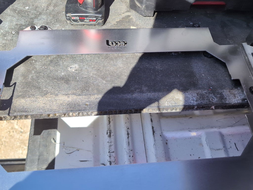
Illustration for Unlock Precision: Advanced DXF Optimization Techniques for Superior CNC Fabrication Results
- Avoid exporting title blocks and borders; keep only the cut geometry.
Open, overlapping, or duplicate paths
- Open contours where a perimeter should be closed will mark instead of cut through, or force manual fixing in CAM.
- Overlapping or duplicate lines cause double cuts, heat buildup, and extra wear. Run a “purge duplicates” check and close gaps within a tight tolerance (e.g., 0.001 in or 0.025 mm).
Unsupported entities and excessive nodes
- Splines, ellipses, and text often convert poorly. Explode text to polylines and convert splines to arcs/polylines before export.
- Arc-to-chord conversion with tiny tolerances balloons node count, creating choppy motion and soot. Balance vector file accuracy with a reasonable chordal tolerance to maintain smooth motion.
Layer discipline and cut strategy
- Unlabeled, mixed-content layers lead to wrong toolpaths. Use clear layers for cut, etch/mark, and bend lines; avoid hidden layers and nested blocks.
- Define inside vs. outside profiles logically to prevent wrong kerf compensation. For small holes, tag as “drill” or “mark” if they’re below practical cut size.
Manufacturability constraints
- Minimum feature sizes must exceed kerf width or tool diameter. Holes smaller than the nozzle/bit will come out undersized or not at all; plan to ream or resize accordingly.
- Internal corners for milled pockets need relief (dogbones/T-bones) matching tool radius; for laser, ultra-acute corners invite heat-affected deformation—add small radii or relief slots.
- Tab width and count matter. Tabs too thin snap; too thick require heavy cleanup. As a rule, size tabs around 1–2× material thickness and place away from critical edges.
Kerf and tolerance
- Skipping kerf compensation yields tight or sloppy fits. Offset profiles in CAM or design nominal-to-fit, considering coating build like powder coat if parts assemble later.
- Pattern alignment is critical. For modular mounting plates, tiny positional errors compound across bolt patterns; lock down hole-to-hole spacing with proper constraints.
2D flattening and export hygiene
- Nonzero Z values, 3D polylines, or splines in a 2D DXF can confuse CAM. Flatten to 2D, purge unused blocks, and save to a widely compatible DXF version.
- Keep filenames, layers, and part IDs clear to reduce errors in the fabrication workflow.
Investing a few minutes here pays back in fewer CAM edits, shorter cycle times, and consistent fits. If you’re optimizing DXF for CNC regularly, build a preflight routine that checks units, closure, duplicates, entity types, layers, and kerf strategy before sending to the machine.
Essential Techniques for Cleaner DXF Files
Cleaner geometry is the foundation of optimizing DXF for CNC. A well-prepared file minimizes pierces, prevents pauses, and reduces post-processing—directly improving laser cutting efficiency and overall fabrication workflow improvement.
Start with standards that eliminate ambiguity:
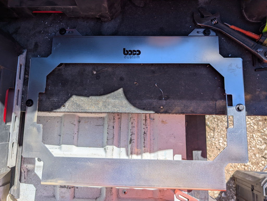
Illustration for Unlock Precision: Advanced DXF Optimization Techniques for Superior CNC Fabrication Results
Units and scale: Work 1:1 in inches or millimeters and confirm the same units are set on export. Avoid mixed-unit blocks. Place the part near 0,0 for predictable nesting.
Z-flattening: Set all entities to Z=0. Any residual 3D data can cause skipped paths or odd CAM behavior.
Versioning: Save to a widely compatible format (e.g., DXF R12/R14 ASCII) when sending to different shops or controllers.
Use geometry your machine and CAM can interpret cleanly:
Prefer polylines and true arcs. Avoid splines, ellipses, hatches, gradients, or raster-based fills. If needed, convert splines to polylines with a sensible chordal tolerance (e.g., 0.002–0.005 in or 0.05–0.12 mm).
Reduce node count. Excessive segmentation produces choppy motion and heat marks. Keep curves smooth with minimal but accurate vertices to protect vector file accuracy.
Eliminate errors that break toolpaths:
Close every contour intended for cutting; CAM often requires watertight loops for inside/outside recognition.
Join segments using a fuzz distance appropriate to your units (e.g., 0.005 in / 0.12 mm). Delete zero-length entities and stray points.
Remove duplicates and overlaps; in AutoCAD, OVERKILL does both without rounding critical geometry.
Organize intent with layers for CNC machining optimization:
Separate operations by layer and (optionally) color—for example: CUT_INNER, CUT_OUTER, ETCH/SCRIBE. Many controllers map process parameters from layers.
Put cut-before-bend markings or etch notes on a distinct layer intended for low power or scribe.
Convert text to outlines for cutting, or use single-stroke (centerline) fonts for etching to prevent unintended fills.
Design for cut quality and fit:
Respect minimum feature size. For fiber lasers on steel, avoid slots narrower than 1.5–2× kerf. Typical kerf ranges 0.010–0.020 in (0.25–0.50 mm); confirm with your shop.
Apply reliefs or small fillets on internal corners where heat concentrates. For routers/waterjets, inside radii must be ≥ tool radius.
Add realistic clearances. Example: If a 0.250 in tab must fit a slot and kerf is 0.014 in, size the slot ≈ 0.264–0.270 in to allow for kerf, material variation, and coating.
Export cleanly from design tools:
Delete title blocks, dimensions, and construction lines before export. PURGE unused blocks and layers to reduce file size.
Explode nested blocks if your CAM doesn’t import them reliably, then re-join as needed.
When exporting from illustration software, disable curve simplification that distorts geometry; set a specific tolerance and verify critical dimensions.
Boco Custom’s instant-download DXF files follow these practices—closed polylines, logical layers, and fabrication-ready tolerances—so you can cut metal plates and mounts with fewer edits. If you modify or create your own, applying the same CAD file preparation steps will produce smoother paths, less heat input, and more consistent parts.
Leveraging Advanced Optimization Software Tools
The fastest gains in optimizing DXF for CNC often come from pairing clean geometry with the right software stack. Use your CAD platform for preflight and repair, then hand off to dedicated nesting and CAM tools that automate pathing, kerf control, and thermal management.
Zero the Z: FLATTEN (AutoCAD Express Tools) or “Explode and set Z=0” workflows to prevent lost entities on import.
Join fragmented vectors: PEDIT/JOIN in AutoCAD, “Join” in QCAD, or “Combine” in Inkscape to create watertight polylines.
Replace splines with arcs: Export arcs/lines only or convert splines to polylines with a controlled tolerance to improve vector file accuracy and smoother motion on controllers that choke on splines.
Standardize units and origin: Lock inches or millimeters and place the part at 0,0 to avoid scaling or off-table moves in the CNC.
Prefer DXF R12 with polylines for broad laser/plasma/router compatibility.
Advanced nesting and pathing software drives real CNC machining optimization:
Nesting: SigmaNEST, ProNest, Lantek Expert, or open-source DeepNest can enforce grain direction, part rotation limits, and kerf-based spacing. Use common-line cutting on parallel edges to reduce pierces and travel while maintaining part quality.
Thermal-aware sequencing: Cut small holes and internal features first, then profiles; alternate zones to shed heat and reduce warp on thin steel or aluminum.
Remnant management: Save and re-nest into skeletons automatically for material yield gains.
Dial in CAM parameters that directly impact laser cutting efficiency and edge quality:
Lead-ins/outs matched to thickness: Short radial leads for thin sheet; longer tangential leads for thicker plate to reduce dross. Avoid leading into corners.
Entry point control: Place leads on non-cosmetic edges or tab locations.
Kerf compensation: Apply inside/outside offsets by operation; verify with a calibrated kerf table per material and thickness.
Microjoints/tabs: Size tabs relative to material and tool; for routers, combine tabs with a light “onion skin” finishing pass to eliminate chatter.
Path order: Inside-before-outside, then nearest-neighbor or “optimize cut path” to minimize rapids. Enable corner smoothing where available to prevent pause marks.
Map named layers (e.g., CUT_INSIDE, CUT_OUTSIDE, ETCH_MARK, DRILL) to specific tool/process settings.
Use a separate layer for bend lines or scribe-only geometry, set to low power or engraving feeds.
Validate before cutting:
Run a backplot/simulation in your CAM to spot tiny segments, backtracks, or missing offsets.
Check the part’s bounding box and key hole diameters against nominal to confirm kerf assumptions.
Cut a single test coupon to confirm fit.
Boco Custom’s ready-to-cut DXF files are engineered to reduce cleanup, so you can leverage these tools immediately instead of repairing geometry. Combined with disciplined software optimization, you’ll cut faster, waste less, and get consistent, repeatable results across jobs and machines.
Maximizing Efficiency in CNC Machining
Efficiency starts with clean geometry. Before export, audit every profile for open contours, overlapping lines, and zero‑length entities. Convert splines to arcs/lines to improve vector file accuracy and avoid over-segmentation that slows the controller. In AutoCAD, use commands like OVERKILL and PEDIT>Join; in Fusion 360, Project and Simplify to remove tiny segments. Keep units explicit (in or mm) and set the origin at the lower-left of the finished part, oriented “cut face up” to match the machine coordinate system.
Adopt predictable layer conventions so downstream steps are automatic. A simple scheme:
CUT: through-cuts, continuous line
ETCH/MARK: low-power etch for bend notes, logos, part numbers
BEND: bend lines and arrows (etch-only)
FORM/TAP: pierce or drill after cutting
Include process metadata in the DXF notes or an etched callout: material, thickness, finish, and revision. For example: “A36, 0.120 in, powder coat, Rev C.”
For laser cutting efficiency, design with the process in mind:
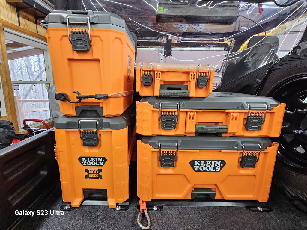
Illustration for Unlock Precision: Advanced DXF Optimization Techniques for Superior CNC Fabrication Results
Lead-ins: place 1–1.5x material thickness, 15–20° angle, tangent to long straight segments. Avoid piercing at acute corners or near small features.
Microtabs: for 0.120 in steel, use 0.040–0.060 in tabs, 2–3 per part side, located on non-cosmetic edges. This stabilizes parts and reduces tip-up.
Part spacing: 0.060–0.100 in between profiles; use common-line cutting only for identical parts where cosmetic edge quality isn’t critical.
Cut order: small holes first, outer profile last. Interlace cuts across the sheet to spread heat and maintain flatness.
Design features for manufacturability:
Minimum slot width: ≥ material thickness + kerf allowance. For 11‑ga steel (0.120 in), target ≥0.140 in to ensure slug removal.
Inside corner radii: ≥ material thickness to mitigate heat concentration and cracking in formed parts.
Hole sizes: clearance for 1/4‑20 = 0.281 in; M6 = 6.6 mm. Add 0.004–0.008 in per side clearance if parts will be powder coated.
Tapped holes: call out tap drill sizes (e.g., 1/4‑20 = #7/0.201 in; M6 = 5.0 mm) on an ETCH layer; avoid tapping in heat-affected, thin edges.
Countersinks: specify angle (82° imperial, 90° metric) and head type; etch icons reduce shop-floor guesswork.
For bend-dependent parts, include bend reliefs (length ≈ 1x thickness; width ≈ 0.5x thickness) and mark bend directions and angles. Provide flat pattern bend deductions or K-factor (0.33–0.42 for air-bent mild steel) to align CAD file preparation with brake programming.
A practical example: when optimizing DXF for CNC for a low-profile mounting plate, replace decorative splines with 3‑point arcs, enlarge Packout-compatible slots to account for coating build, and etch the array datum. You’ll see faster nesting, fewer pierces, and consistent fitment in the field.
These CNC machining optimization steps streamline quoting, reduce rework, and shorten cycle time. Boco Custom’s instant‑download DXF files follow standardized layers, tuned kerf allowances, and bend annotations to plug directly into laser workflows—accelerating fabrication workflow improvement without sacrificing accuracy.
Future Trends in Digital Fabrication
Digital fabrication is moving toward smarter files, adaptive machines, and connected workflows. For teams optimizing DXF for CNC, the next few years will focus on embedding intent in vector files, automating preflight, and using machine feedback to improve every subsequent cut.
Key trends to watch:
Semantic DXF conventions: Shops are converging on standards that encode process intent in layers and colors. Expect wider use of layers like CUT_10GA, ETCH_TEXT, BEND_UP, and MARK_QR to drive automatic CAM rules. Extended data (XData) in DXF can carry material, thickness, kerf target, and tolerance notes so lasers, plasmas, and waterjets apply the right strategies without manual edits.
AI-assisted CAD file preparation: Preflight tools will evolve from basic error checks to true optimization. Models will automatically close tiny gaps, remove duplicates, convert splines to arcs with controlled chordal deviation, and round micro-features below nozzle diameter. This reduces machine decel events and boosts laser cutting efficiency on dense patterns.
Parametric DXF generation: Configurable part families will let fabricators download fit-for-purpose files. For example, mounting plates with selectable hole patterns, slot clearances, and material thickness can be generated on demand, avoiding redraw time and ensuring consistent vector file accuracy across variants.
Closed-loop CNC machining optimization: Controllers will feed back cut quality, heat input, pierce reliability, and tip-up incidents. CAM will adapt lead-ins, micro-tab size, corner smoothing, and kerf compensation by material lot and thickness. Expect variable kerf maps and direction-aware compensation to become standard for thin sheet work.
Cloud-native nesting and scheduling: Multi-job, multi-material nesting will leverage common-line cutting, part-in-part placement, and skeleton-first removal sequences to cut faster and safer. Real-time scrap mapping will reuse remnant outlines; scheduling will align cut order with press brake availability to streamline fabrication workflow improvement.
Lightweight, precise vectors: Clean geometry remains critical. Future exporters will snap coordinates to machine resolution, unify polyline direction, and enforce maximum vertex spacing for smooth motion. A practical target is maintaining arc-fit error under 0.05 mm while limiting node count to keep controller buffers happy.
Process-aware exports: Single DXF files will drive multiple operations via standardized layers for etch text, countersinks, pierce points, bend lines, grain direction, and powder-coat masks. Engraved QR codes linked to routers or ERP will improve traceability and kit accuracy.
Security and provenance: As files move across vendors, expect checksum verification and optional watermarking so recipients know a file is the approved revision before cutting.
For professionals, these trends reduce prep time and scrap while elevating consistency. Providers of instant-download DXF files can embed layer standards, pre-placed lead-ins, and documented kerf assumptions so shops can load, nest, and cut with minimal CAM touch-up. The result is faster quoting, fewer surprises on the table, and superior CNC machining optimization at scale.
Achieving Unparalleled Precision and Quality
Precision on the table starts with precision in the file. Optimizing DXF for CNC is less about pushing buttons at the machine and more about disciplined CAD file preparation that eliminates ambiguity, prevents rework, and preserves intent across different processes.
Start with clean, unambiguous geometry:
Work 1:1 in the correct units (in or mm) and note the unit in the file name.
Flatten all entities to Z=0. Remove duplicates, zero-length entities, and stray construction lines.
Join into closed polylines for profiles; avoid self-intersections. Convert splines to arcs where possible to improve laser cutting efficiency and path smoothness.
Save to a widely compatible DXF flavor (many shops prefer R12/LT2) to avoid spline/ARC translation issues and preserve vector file accuracy.
Control operations with layers and colors:
Separate layers for cut, etch/mark, bend lines, counterbores, and center marks. Lock non-cut layers.
Use consistent color mapping (e.g., red = exterior cut, yellow = interior, blue = etch) to streamline CAM and support fabrication workflow improvement across vendors.
Design in tolerances and machine realities:
Account for kerf and tool diameter. Typical fiber laser kerf is 0.004–0.012 in (0.10–0.30 mm); CNC routers follow the bit radius; plasma is larger (≈0.040 in/1.0 mm). Offset internal profiles outward and external profiles inward if the CAM won’t compensate.
Add dog-bone or T-bone reliefs on internal 90° corners for router-cut parts so rectangular parts seat fully.
Size holes to the process: tapped holes are piloted; clearance holes should include coating. For example, an M6 rivnut often needs 0.362–0.366 in; allow an extra 0.004–0.008 in if powder-coated.
Include corner reliefs at slot ends to reduce stress risers and prevent cracking in thick plate.
Plan entry, exits, and heat:
Define pierce points and lead-ins away from corners and fine features. Short (0.05–0.10 in), shallow-angle lead-ins reduce edge blemishes.
Use micro-tabs on small parts to prevent tip-ups; place tabs where post-processing is easiest.
For thick or heat-sensitive material, stagger small features and long cuts to minimize thermal distortion.
Nesting and datum strategy:
Maintain consistent 0,0 at the lower-left of the part or sheet. Add two tooling holes or etched datums for repeatable fixturing.
Nest with kerf-aware spacing and grain direction in mind if finish or strength is directional.
Validate before you cut:
Add a “QC” layer with critical dims and GD&T notes. Print a 1:1 paper template to verify critical patterns (e.g., a Milwaukee Packout bolt grid) against the physical component.
Run a geometry audit in CAD/CAM to flag open contours, overlaps, and tiny segments that inflate cycle time.
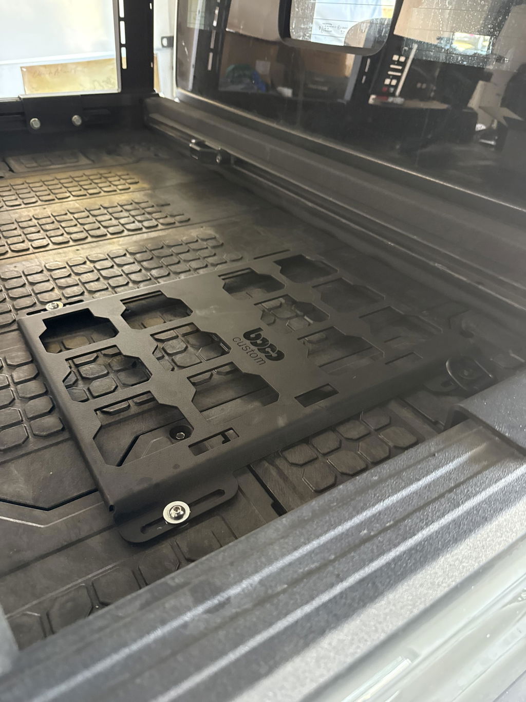
Applied example: For a low-profile mounting plate, convert the Packout pattern to closed polylines, assign etch for logos and bend lines, set M5 clearance holes to 5.4–5.6 mm if coating is applied, add 0.125 in dog-bone reliefs in routered pockets, and specify 0.06 in lead-ins on long exterior cuts. This combination of CAD file preparation and CNC machining optimization reduces cut time, improves edge quality, and ensures bolt-up without post-drilling.
Boco Custom’s instant-download DXF files follow these practices out of the box, enabling faster CAM, fewer edits at the machine, and consistent, bolt-on results for professional tool storage systems.
Standard shipping takes 5 to 7 business days. Express (2 to 3 days) and overnight options are available at checkout. Orders over $50 ship free.
Can I order online and pick up in store?
Yes. Select "Pick up in store" at checkout and choose your nearest location. Most orders are ready within 2 hours.
What if my order arrives damaged?
Contact us within 7 days of delivery with your order number and a photo. We'll arrange a replacement or refund, no return shipping required.
AI-Generated Content Disclosure
This blog post was created with the assistance of RankGPT, an AI-powered tool designed to generate high-quality, SEO-optimized content at scale.
As a small business embracing modern technology, we use AI to help us:
Produce informative articles more efficiently
Increase our online visibility through better performance in traditional search engines (like Google) as well as emerging AI-powered searches and answer engines
Reach more potential customers and grow our presence in a competitive digital landscape
By leveraging tools like RankGPT, we're able to publish valuable content more consistently and scale our efforts in ways that would otherwise take significantly more time and resources.
Important notes for readers:
While RankGPT helps create well-structured and relevant content based on current best practices, AI-generated posts are not always 100% accurate, complete, or free from errors.
The information, opinions, and perspectives expressed may not fully reflect the exact views, experiences, or official positions of Boco Custom, its team members, or the individuals involved in our business.
AI content should be viewed as a starting point or general resource—not as personalized professional advice, definitive facts, or a substitute for direct consultation with us or qualified experts.
We always recommend verifying important details independently, especially for decisions related to custom products, services, or any business matters.
We are committed to transparency and continually work to improve our content. If you have questions, feedback, or spot any inaccuracies, please reach out—we genuinely appreciate it!
Not only is this way overbuilt for the price with its solid, confident craftsmanship, I am completely convinced that these guys are the best around when it comes to the packout platform.
I like these, they are much more compact than what Milwaukee offers. I had them powder coated in silver vain and they look awesome. I love the bonus half rack they sent me. That’s the mark of a nice company.


Leave a comment